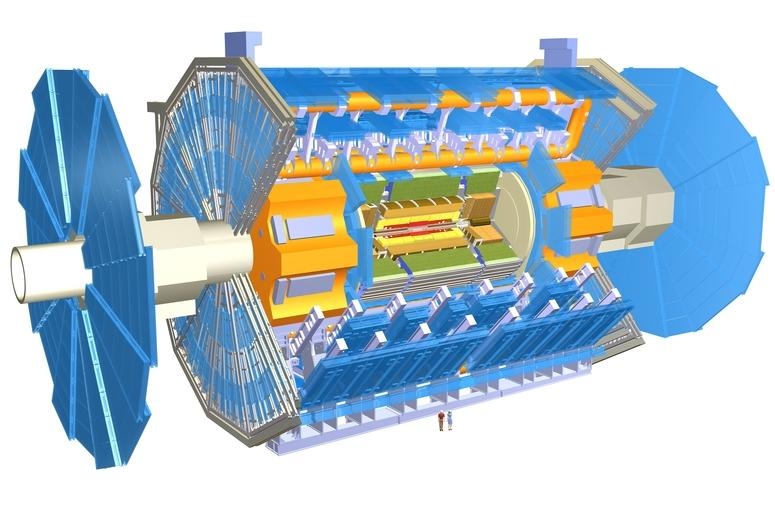
Infrared images of ESLI prototype sector 8

The coolant fluid was water. The ambient temperature was approximately 28° C. The "A" side of the sector was coated with a white paint to give a uniform emissivity. The temperatures indicated by color of the "A" side are accurate to within one half degree and were checked by RTDs at several locations. The "B" side was not coated with white paint, hence the temperatures indicated by color are not as accurate as those of the "A" side. Refer to the photgraph of ESLI sector 8 to aid in interpreting the infrared images.

"A" side image with no simulated electronics power applied. Coolant flow was 10 cc/s. Coolant inlet temperature was 21.1° C
"A" side image with 18 Watts simulated electronics power applied to each side. Coolant flow was 10 cc/s. Coolant inlet temperature was 21.0° C. Approximately 10 degree wide temperature color scale
"A" side image with 18 Watts simulated electronics power applied to each side. Coolant flow was 10 cc/s. Coolant inlet temperature was 21.0° C. Approximately 20 degree wide temperature color scale
"A" side image with no simulated electronics power applied. Coolant flow was 20 cc/s. Coolant inlet temperature was 20.7° C
"A" side image with 18 Watts simulated electronics power applied to each side. Coolant flow was 20 cc/s. Coolant inlet temperature was 20.7° C. Approximately 10 degree wide temperature color scale
"A" side image with 18 Watts simulated electronics power applied to each side. Coolant flow was 20 cc/s. Coolant inlet temperature was 20.7° C. Approximately 20 degree wide temperature color scale
"B" side image with no simulated electronics power applied. Coolant flow was 20 cc/s. Coolant inlet temperature was 20.5° C
"B" side image with 18 Watts simulated electronics power applied to each side. Coolant flow was 20 cc/s. Coolant inlet temperature was 20.6° C. Approximately 20 degree wide temperature color scale


Questions and comments to:
DLBintinger@lbl.gov
fmccorma@sts.lbl.gov


AC